In many cases, a controller for switching the speeds of fans installed in fan coil units or other fans with three different rotation speeds is included with the unit purchased. If it is not an accessory or e.g. broken or other control methods are needed, then individual solutions may come into question, as we have already shown in our articles. There is typically no control cable for wired control of retrofitted fan units. To install the control cable, it is essential to have a carving or an external, not very aesthetic cable duct.
Fortunately, the iNELS Wireless system offers several tools and useful features to solve this problem in a complex way, including control from a smartphone, even within a complete smart home system. The following are examples of wireless methods with different locking and timing options. The easiest way to lock the circuit-breaker hardware with changeover contacts is to use 4 - 5 - 6 changeover relays on the
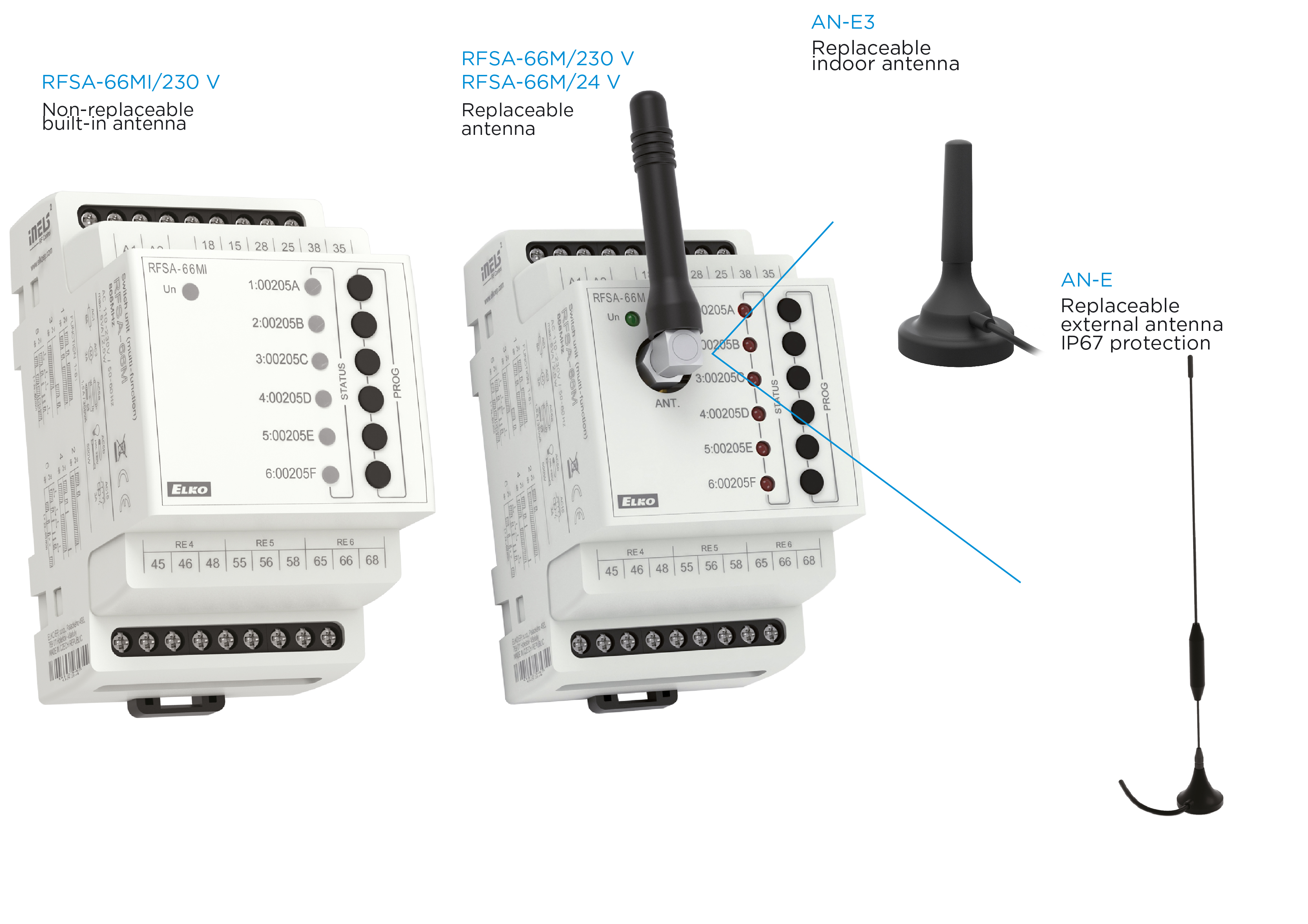
RFSA-66M or the recently released
RFSA-66MI six-channel switch (relays 1 - 2 - 3 are only closing contacts).
There are two main differences between the two switching units:
- The letter “M” in the type code for both refers to the modular design, but the unique “M” has an external stick antenna. It follows that the antenna marked "M" can be replaced (AN-E indoor or AN-E3 outdoor), so it can be installed in a metal cabinet.
- The "MI" type has a built-in antenna and cannot be replaced, so it is recommended to install this type in a cabinet with a plastic or plastic door. It is more cost-effective due to the lower price range (but not recommended for metal cabinets!)
Remote control
The lack of control wires or wiring difficulties (eg wall engraving, sewerage) can be overcome relatively easily with radio frequency devices. The following picture shows the three speeds of the fan coil fan with three changeover contacts of the six-channel RFSA-66MI. With one or even more RF controllers - in this example, we use a controller that can be mounted on a black glass RFGB-40/B wall or flat surface.
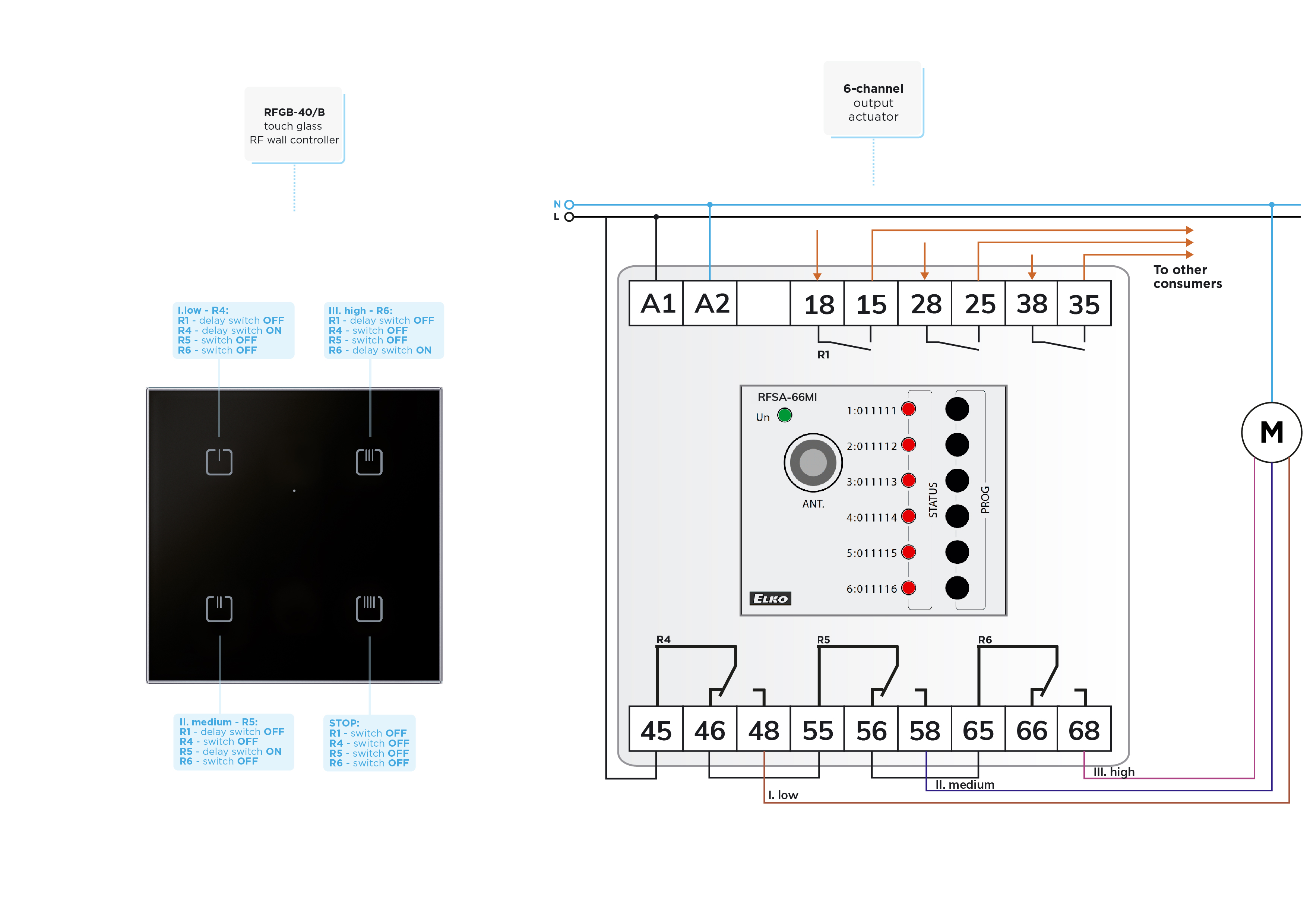
The RFSA-66MI (or RFSA-66M) relays can be paired independently with each button on the controller. The motor’s coils are connected by the closing contacts of the changeover contacts, the breaking contacts are used for locking.
There are two ways to lock the gears at the same time:
-
By connecting the rest contacts of the changeover contacts in series (logic AND connection), a hardware interlock is obtained, so that only one switched-on coil can receive voltage at a time. In principle, it is possible that with the activated III. coil the II is also switched on, but due to the physical lock only II. grade will work. With proper pairing and faultless RF communication, this cannot happen.
-
Another level of interlocking is provided by pairing the control buttons with the relays as follows:
- Button 1: Delayed activation of the I. relay (function 6), the same button press switches off the II. and III. relay (function 3).
- Button 2: Delayed activation of the II. Relay (function 6), the same button press switches off the I and III relay (function 3).
- Button 3: Delayed activation of the III. relay (function 6), the same button press switches off the II. and II. relay (function 3).
- Button 4: STOP function, switching off the fan by switching off all three relays (function 3)
With the delay used to switch on each coil, we wait for the coil that is already powered to be switched off. The three unused relays can be used to switch additional consumers with other controllers.
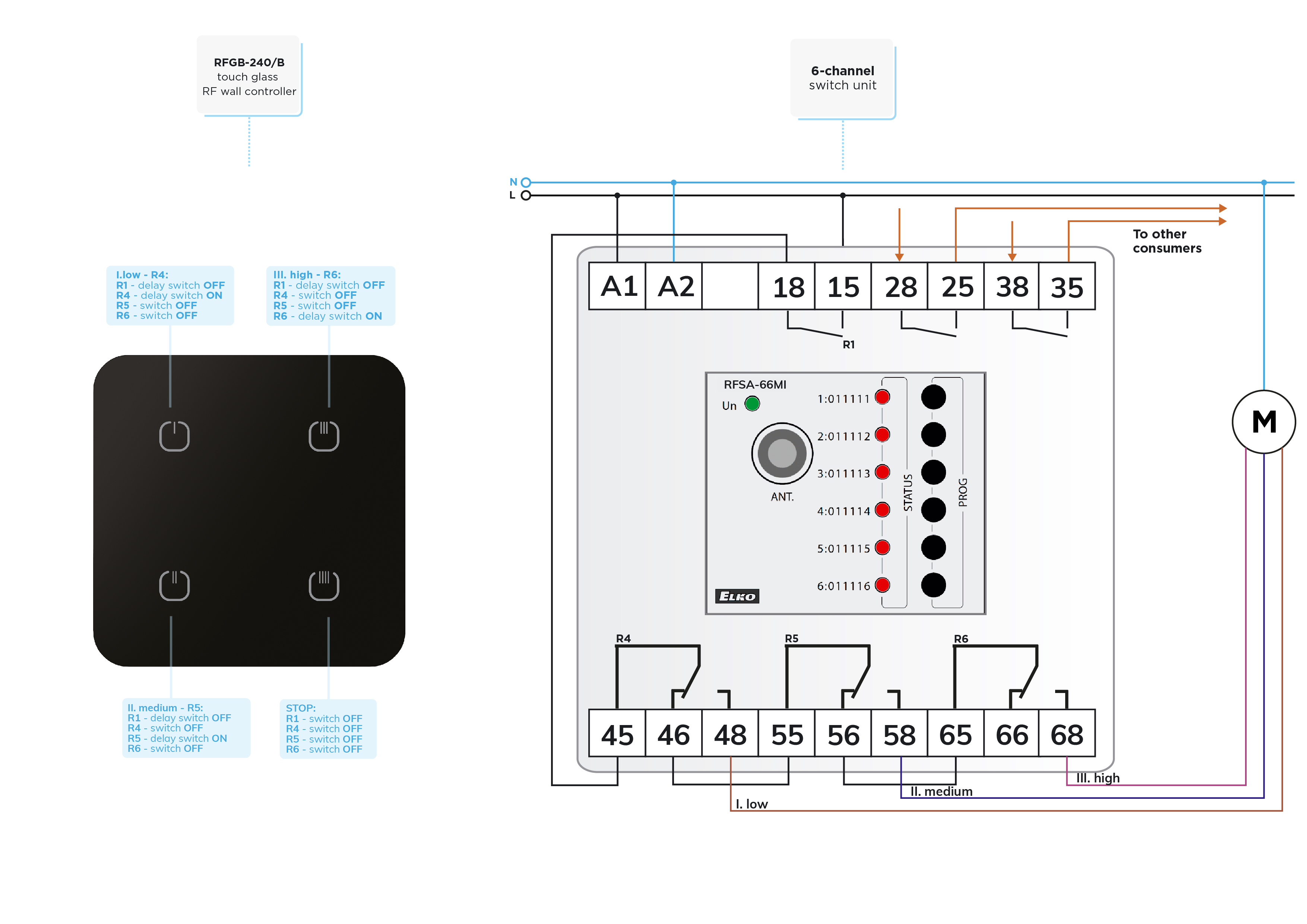
Remote control with separate relays to switch off
In the circuit shown in Figure 3, two changes can be detected compared to Figure 2. One is the type of controller (
RFGB-240/B), which was made only to illustrate the wide selection of controllers. The difference compared to RFGB-40/B is in the design. The 40/B has square corners, while the 240/B has rounded corners. Another difference is that the power supply of the switching relays is not fixed, but also with an RF relay, increasing the safety of the switch-off.
An interesting option is obtained by pairing the fourth button of the controller only to turn the power relay on and off (function 4) and not turning the other relays off with it as shown in the figure. This allows the last chosen speed to operate when switching back on. Another option is to keep the status of the relays after a power failure by setting the "MEMORY" function per channel. Then, after a power failure, all memorized relay outputs switch to the state before the power failure.
Timing control
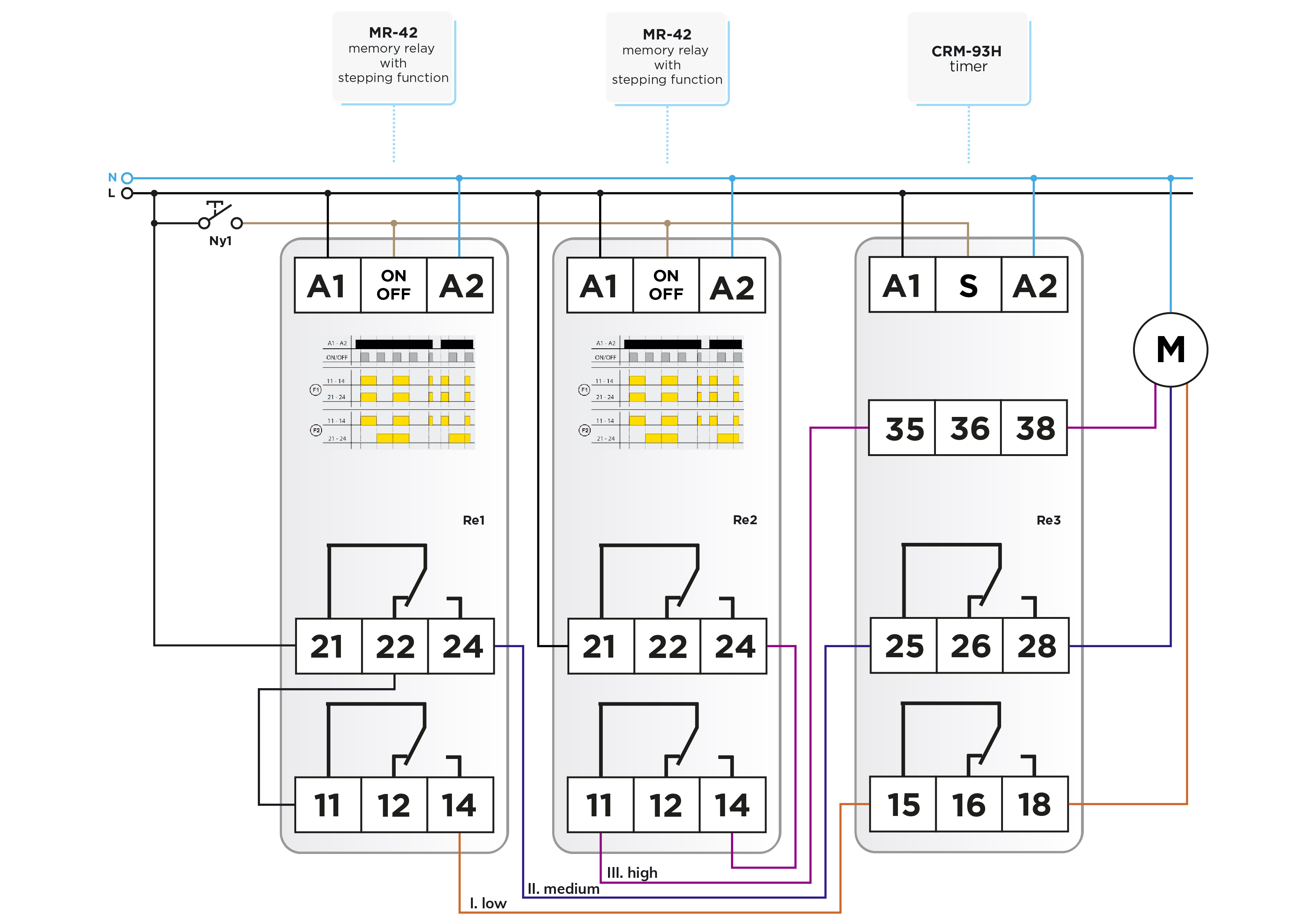
The previous switches can simply be supplemented with a timer function so that the fan switches off after the set time when any coil is switched on. Figure 4 uses a CRM-93H three-output multi-function time relay.
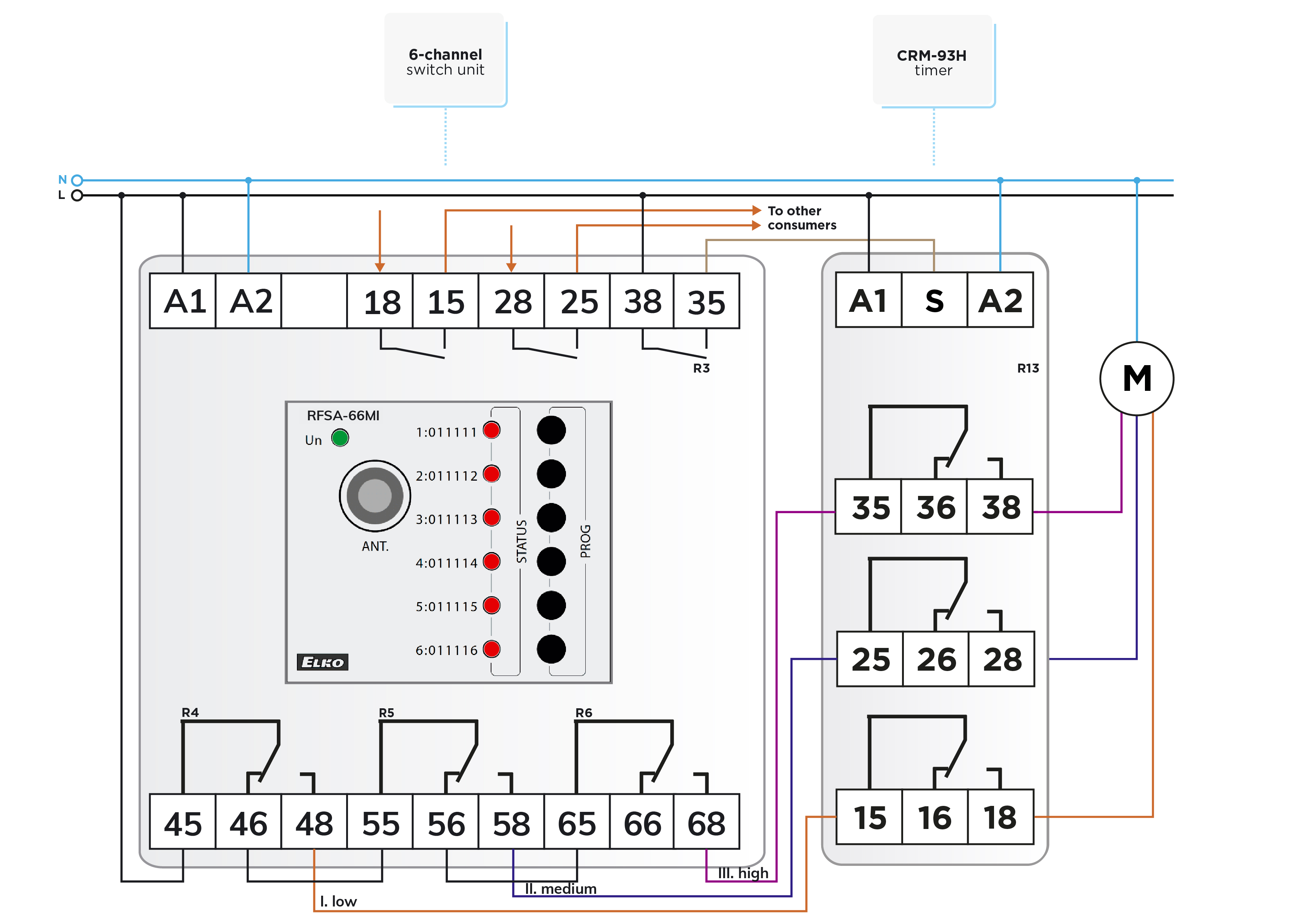
The relays of the time relay operate simultaneously, but their potential-free contacts are independent of each other. The three-time relay contacts transmit the signal of the closing contacts of the RF relays of the three coils simultaneously, but only the active coil will be energized. By setting the time relay to function “e”, a restartable delay switch-off is obtained. The R3 relay of the RF switching unit gives a control signal to the "S" input. The relays are pulled to the rising edge of the signal appearing at the “S” input, the timing starts with the relay pulled into the falling edge, and after that, the relays of the time relay are switched off. Another possibility for timing is to pair relay R3 to switch off delay function 5 to button 4 of the controller in the circuit of Fig. 3.
Timing for previous connections
For the sake of completeness, Figure 5 shows the use of the CRM-93H time relay for the solutions discussed earlier.
In our next letter, we will come up with more interesting things.
Attention! The solutions presented in the articles are illustrated with conceptual circuit diagrams in which, despite repeated inspections or tests under workshop conditions, errors may occur. It is the installer's task and responsibility to check their suitability for a given task and to make any changes! The author and the company do not accept any liability for damages or other problems resulting from the use of the presented solutions. The colors of the wires in the drawings only help for easier transparency, they do not necessarily match the colors of the standard wiring.

 E-shop