Everyone buys all kinds of electronic devices for their homes, including appliances with microelectronics, because everyone wants the smartest devices and preferably multifunctional ones. However, few people think about the fact that these devices can fail for simple reasons if they are not adequately protected.
Such a simple reason can be, for example, overvoltage or even a voltage lower than the operating voltage, or in the case of three-phase devices, phase loss or phase sequence error (the probability of the latter is small, but not zero!). In any case, it is advisable to install basic lightning and surge protection.
Most electronic devices do not like to be powered back on too quickly after being turned off. This can be e.g. also a short-term, quickly recovering power outage. When the network is restored, most devices will go into standby mode, but their circuits should still function without errors. The operation of electronic devices is most likely ensured by some kind of microprocessor or microcontroller circuit.
For the program of such a circuit to be able to start safely after switching on, a so-called "RESET" process must take place before running the program, during which the supply voltage of the internal circuit parts is stabilized and the registers (internal status stores) are reset. If an error slips into this start-up process, the operation will not start in a good case, the device will “go crazy” in a worse case, and it will fail permanently in an even worse case. One of the basic conditions for the correct "RESET" process to take place is that it starts when the supply voltages are almost eliminated and the capacitors and stray capacities are discharged.
Switching on and off too fast can be so fast that the circuits do not have enough time to get to the basic state required for the "RESET" process, so it is started from some intermediate, unstable state, therefore the "RESET" will be faulty. The above restart problem can occur not only with electronic devices. Refrigeration machines and refrigerators do not particularly like such effects - an abnormality in the pressure conditions of the refrigerant can even destroy the compressor (in this case it just hums, its current consumption increases and it does not cool). But we can also classify air conditioners here. Of course, manufacturers include some kind of protection, but this may not help in all cases.
The simplest way to protect is to install a voltage monitor that matches the nature of the device. ELKO EP offers several types of voltage monitoring relays for monitoring different characteristics for both single and three phases. All of our voltage monitors are suitable for phase loss monitoring. We manufacture complex devices that, in addition to monitoring the adjustable maximum and minimum voltage levels, also check the phase sequence and asymmetry.
But we also have tools that monitor different combinations of the features listed above, so that you can choose the protection most needed for your application. Depending on the device, there are two types of power supply for the voltage monitoring relays: a separately connected power supply or the connection points of the monitored network are also power supply inputs. The relays of the voltage monitors are in the default state - when the monitored characteristics are OK - in a closed state (coil of output relay is energized), so they are active. And when there is something wrong, they are inactive (the coil of the output relay is not energized).
This mode of operation clarifies the error since the relays of devices with separate power supplies are also released when the power supply is off. The HRN-35 type is an exception because it works the other way around: it relays close (the coil is energized) when there is a fault, so it can be used primarily for signaling and other controls.
With voltage monitoring relays, with the correct setting and installation, we can therefore protect our devices from low or overvoltages, phase loss, phase sequence change, and asymmetry errors, but they do not protect against too fast reconnection. Because only a one-time element can be set: the fault detection delay, which serves to ensure that short-term disturbance signals, voltage spikes, etc. do not cause unnecessary switching on/off.
What about switching back? The switchback for all voltage monitors is hysteresis-based, which is usually a fixed factory value, or adjustable for some devices (e.g. 5 or 10%), but not timed for any of them. However, the hysteresis may not be sufficient for the problem mentioned in the introduction, since its time value depends on the speed of the signal change, which is typically quite fast. Two solutions are possible. For one, we use a voltage monitor that also has a so-called "MEMORY" function (for 1-phase: HRN-41, HRN-42; for 3-phase: HRN-43 types). If this function is on and the device has an error, it only switches back on after pressing the RESET button on the front panel, so switch it back on manually. The other solution is simpler and automatic: put a time relay on the output.
In Figure 1, the HRN-33 single-phase voltage monitor was supplemented with a CRM-91H multi-function time relay.
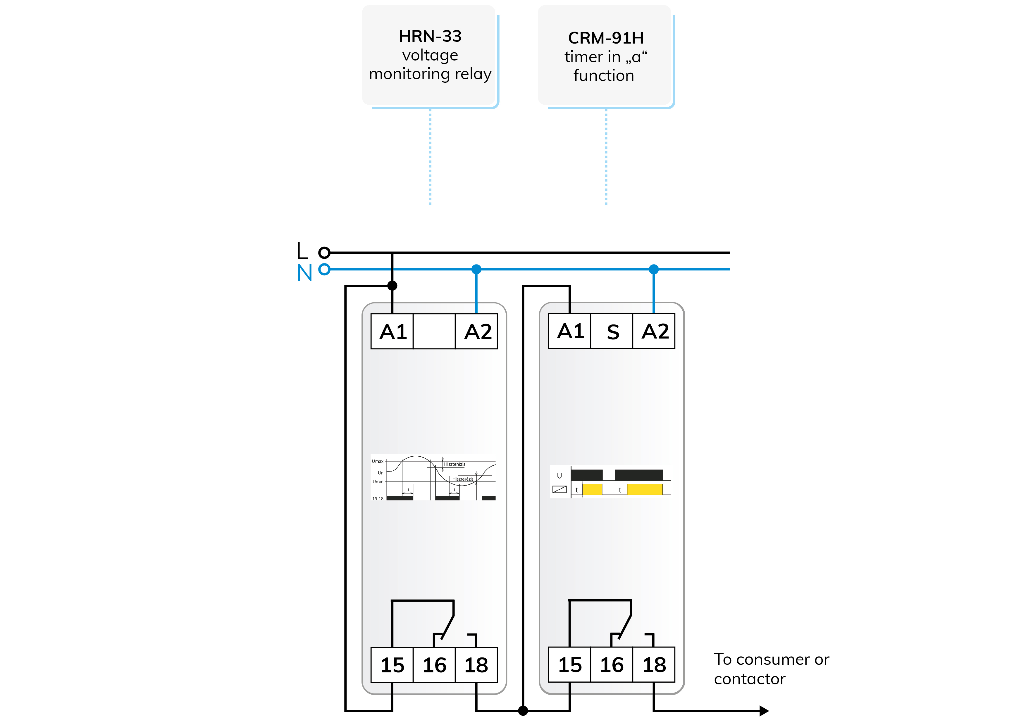
The HRN-33 also receives its supply voltage from the monitored network and has a single relay output, which is connected when the monitored voltage is in the set Umin - Umax "window". If the voltage leaves the window and this state persists even after the set delay, the relay releases. If the voltage is restored and enters the window again, the relay switches back with hysteresis.
The time relay receives power to switch back on. The time relay is set to "a", voltage-start delay switch-on function and timing appropriate for the application. After the delay, the time relay turns on the supply voltage of the protected device (directly or via a contactor).
The duration of the delay would be determined by the protected device if we knew the shutdown duration required for a stable "revival", but we probably won't get this on the data sheets, but an approx. 30 - 90 seconds can be safely sufficient for most devices, it may be worth waiting longer for refrigerators, up to 5 - 30 minutes depending on the refrigerator.
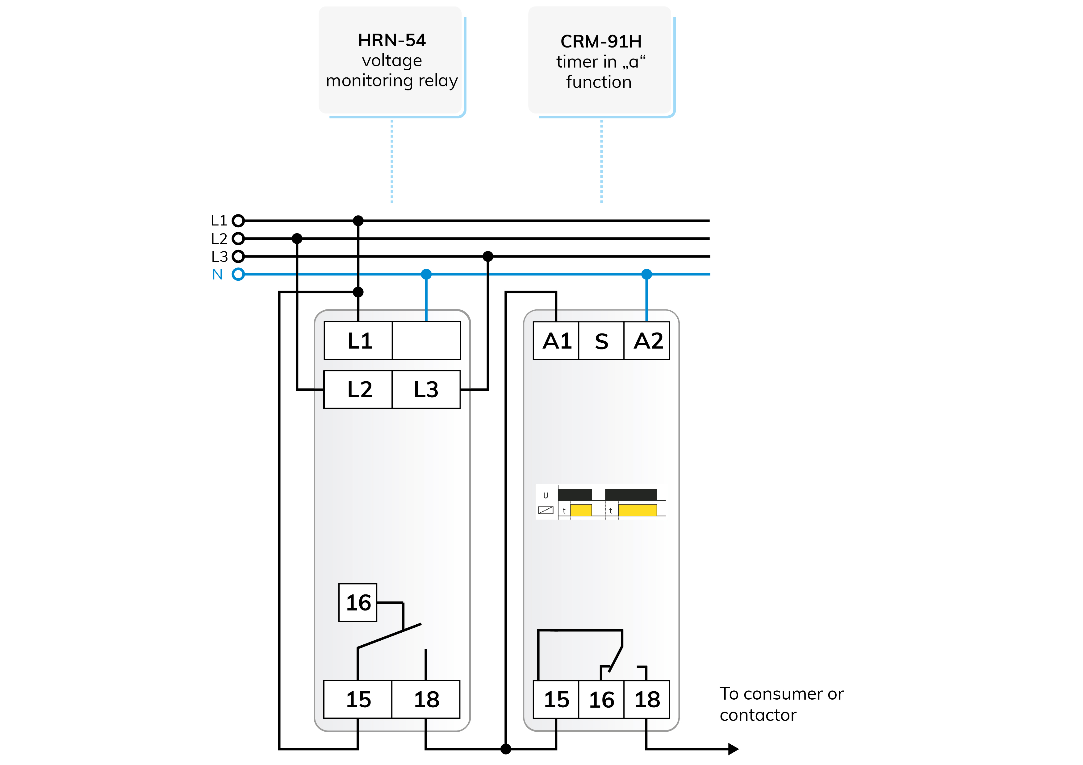
Figure 2 shows a connection similar to the one above but with the HRN-54 type 3-phase voltage monitor (the HRN-54N type can also be used, which also monitors zero). The operation is clear, so we will not go into further detail.
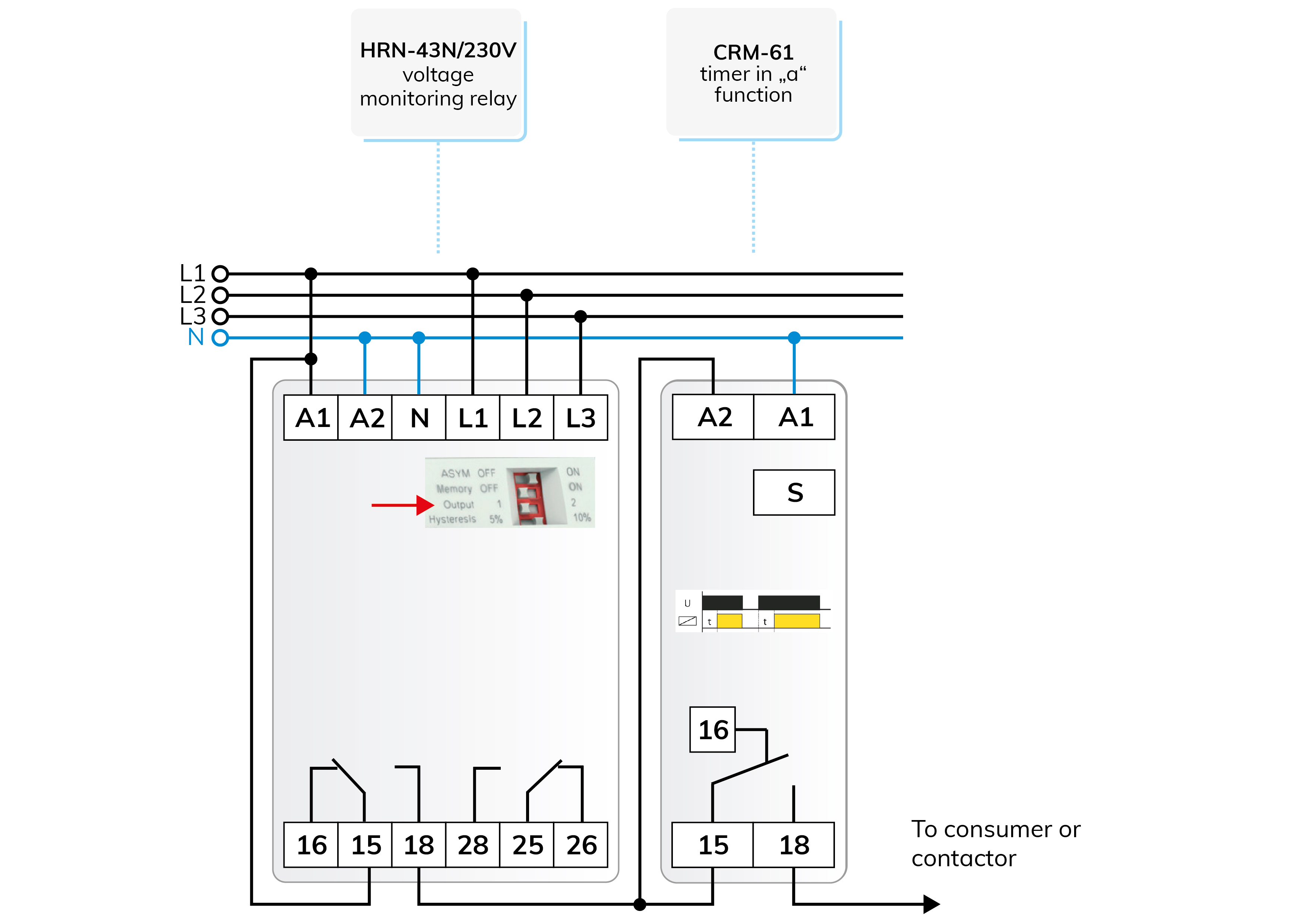
The voltage monitors presented so far signaled error states with a single relay. The HRN-43/230V or HRN-43N/230V 3-phase types have two relay outputs. In position 2 of the "Output" DIP switch on the front panel, one relay releases when any of the monitored voltage inputs exceeds Umax, and the other relay releases when it falls below Umin.
When the "Output" switch is in position 1, the relays work in parallel, so both will be released for any error. In case of phase sequence, asymmetry and phase loss errors, both relays release regardless of the switch position.
1. We set the "Output" switch to position 1, the relays work in parallel, so we can start the time relay with either one (see Figure 3). This setting can be used when there is no need to treat undervoltage and overvoltage faults separately.
2. The “Output” switch is set to position 2, so the relays operate separately and a distinction can be made between low and overvoltage faults (see Figure 4).
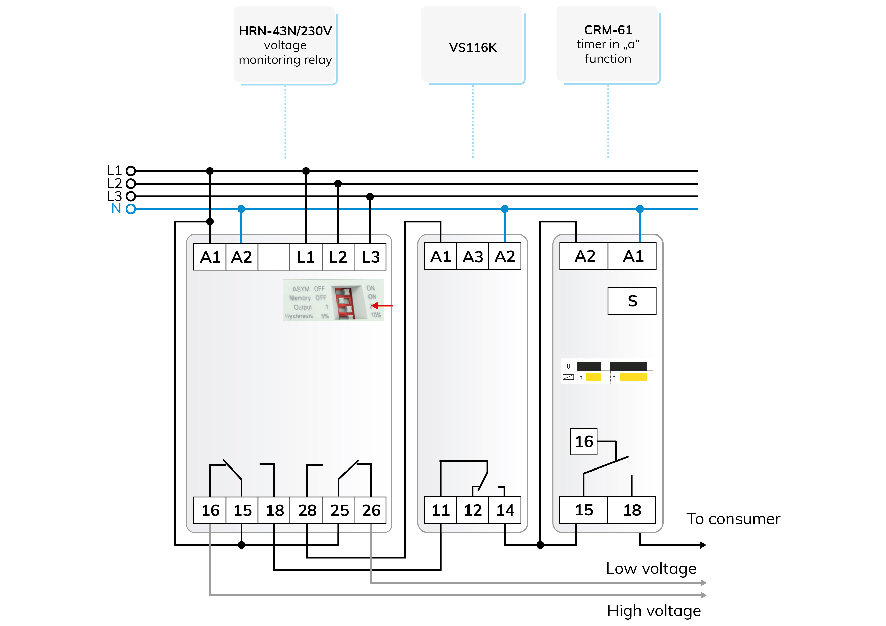
To differentiate between the two voltage errors, we also included a VS116K type auxiliary relay, with which we make "AND" logic between the two channels without disturbing the independent operation.
The "AND" connection comes together in such a way that the auxiliary relay receives power if the voltage on neither phase is lower than the Umin value, but the common point (11) of its relay also receives voltage only if there is no overvoltage on either phase, so both conditions must be met is required to start the time relay.
Attention! The solutions presented in the articles are illustrated with schematic circuit diagrams, which may contain errors despite repeated checks or tests under workshop conditions. It is the duty and responsibility of the installer to check and possibly modify their suitability for a given task! The author and the company assume no responsibility for damages and other problems resulting from the use of the presented principle solutions. The colors of the wires shown in the drawings are only for easier transparency, they do not necessarily match the colors of the standard wiring!

 E-shop