In addition to institutions, larger buildings, and office buildings, the need for hot water from multiple locations is also common in family houses and flats. It's not uncommon for more than two or three rooms to require hot water. If the hot water production is relatively far from these taps, then the cold water must be allowed to flow freely until the hot water arrives.
Drinking water remains valuable, but some predictions suggest it could become a source of serious conflict when it's no longer available in good quality in many places. Apart from an occasional hosepipe ban, we are fortunate in our country today, but excessive water consumption affects our wallets.
In this letter, we present two solutions for timed control of the bypass branch pump for buildings with more than two hot water intakes. Both circuits are controlled by the existing lighting switch in such a way that not only the timing of the pump operation is regulated but also it starts with a delay. The purpose of the short delay is to prevent the pump from starting immediately when the lights are switched on due to a brief visit to a room. The operating time of the pump must be set to ensure the hot water circulates through the piping system.
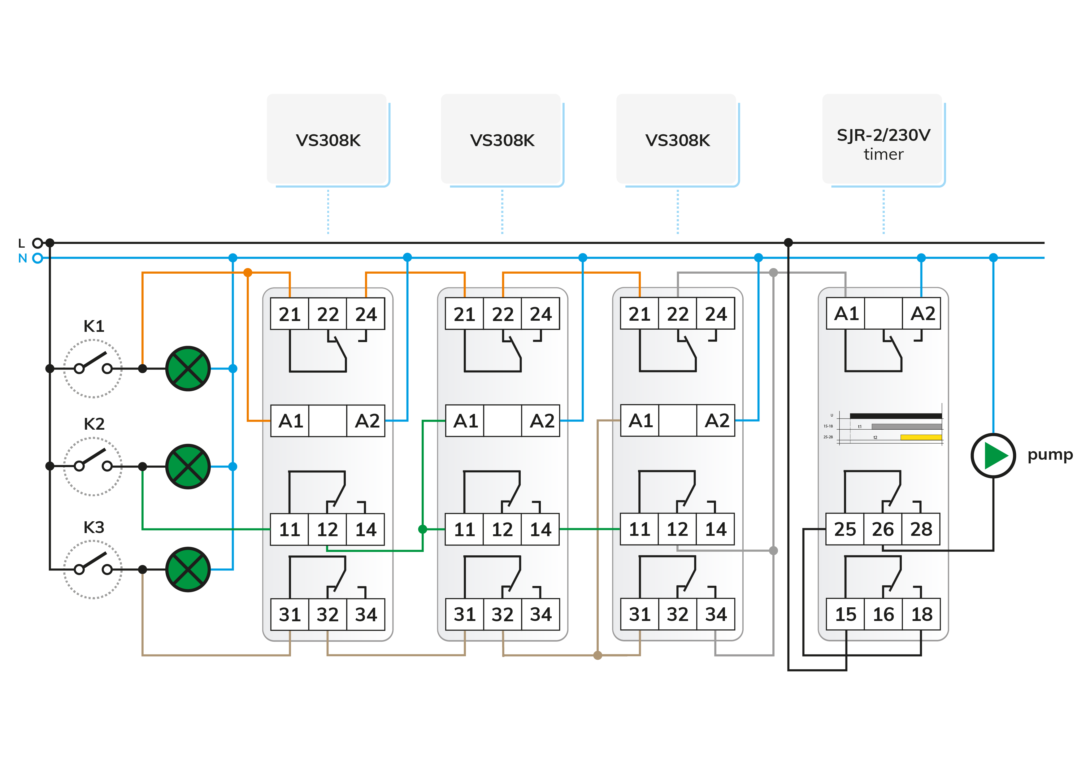
Although not employed in its basic function (timed switching of loads), the time relay is used here to regulate the delay and operating timing required for the circuit using a single device. The two independently adjustable timers start simultaneously upon the power supply being switched on. The duration of channel 1, "t1," determines the delay before the pump starts by the activation of the lights. If the lights are switched off during this time, the process will be interrupted.
If individuals continue to occupy the room after the "t1" delay, the relay of channel 1 energizes and connects the voltage at terminal 18 to the common contact 25 of channel 2, which is also accessible via idle contact 26. Consequently, the pump activates. Upon the elapsing of timer "t2," relay 2 energizes and turns off the pump. Consequently, the pump's operational duration equals the difference between the two values, i.e., t2-t1.
The direct utilization of electronic components isn't a widespread practice in everyday electrical installations. However, the diode stands out as a remarkably simple component. While primarily employed for rectification, we've previously introduced diode logic circuits in our correspondence, streamlining the creation of OR connections.
The viability of diodes became feasible with the introduction of so-called UNI-powered devices. However, caution is advised!
Not all manufacturers' use of the term "UNI" aligns with the typical specifications found in ELKO UNI power supply data sheets. A UNI power supply device refers to one whose power source can be linked to the same two supply terminals within the AC/DC range of 12 to 240 V while maintaining full functionality.
When applying 230 VAC to a UNI power supply via a diode, approximately half of the effective voltage will register at the device's power input, as the diode permits only one branch of the sine wave (effectively functioning as a one-way rectifier). For mains voltage, a diode with an appropriate voltage rating must be selected - in this case, we've denoted the 1N4007 type, rated at 1 A and 1000 V.
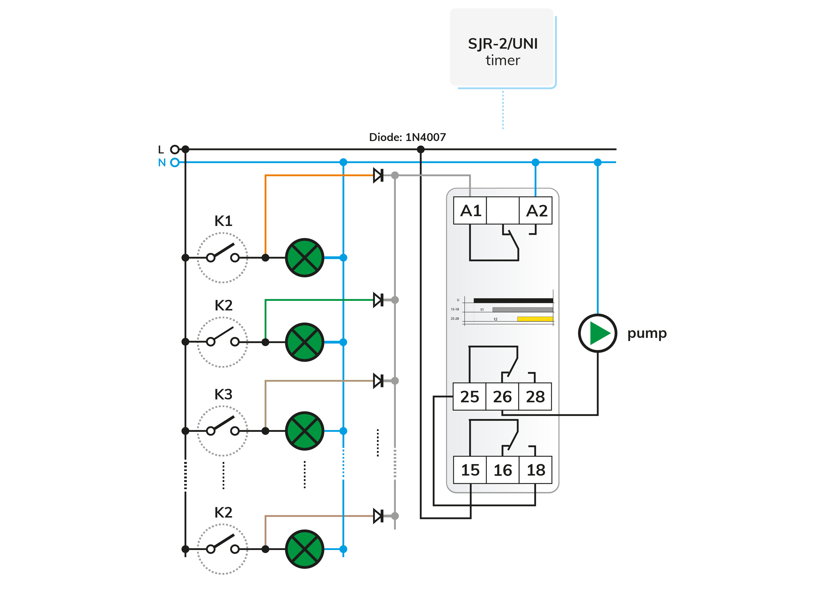
The timing is facilitated similarly using an SJR-2 time relay, albeit with a UNI-powered variant (SJR-2/UNI) to accommodate diodes. When using a 230 VAC powered version, the circuit fails to operate due to insufficient supply voltage and pulsating DC.
The time relay can draw power from any switch via diodes connected to the logic OR, enabling either switch to initiate the process. If all switches (lights) are turned off during timing, the pump deactivates. In cases where individuals briefly occupy one room but activate the lights in another, the ongoing process continues uninterrupted and restarts.
The anodes of the diodes are in the direction of the switch, while the cathodes are common, ensuring the rectified signal cannot supply reverse voltage to other light sources. This setup even prevents, for example, an LED from blinking.
Although it's not recommended to connect diodes with mixed polarity, they can still be linked to the switch with cathodes if they are uniformly oriented.

 E-shop