Impulse relays are excellent alternatives for lighting control from multiple locations, but they have not defeated the traditional alternative - crossover switch solutions, one of the reasons for which is perhaps the additional devices, more wires and the additional costs of installation. With the appearance and rapid spread of "smart house" systems, their popularity further worsened, since an "intelligent" system is also capable of pulse relay operation by default. But not everyone wants a complete "smart house", but some "smartness" for more comfortable control would greatly improve the system.
One such need is when several lighting circuits are installed, e.g. in the common large space of the living room-kitchen-dining room, which of course they would like to control separately, but an "All On" and "All Off" function would also be useful. Special pulse relays with a common control input are also available, ... but let's face it, it would be too easy with these, there is nothing challenging about it.
In Figure 1, six lighting circuits are controlled with pulse relays, so that the individual circuits can be controlled separately, independently of each other, or in group. In order to function correctly, we have to use slightly different solutions from traditional pulse relay installations. The first thing that can be noticed is that it is not a normal push button for the separate control of each circuit, but push buttons with changeover contacts - such as e.g. type 21151 available in the LOGUS90 design. The reason for its use is to separate the individual controls from the common control wires. In a basic situation, therefore, priority is given to joint control.
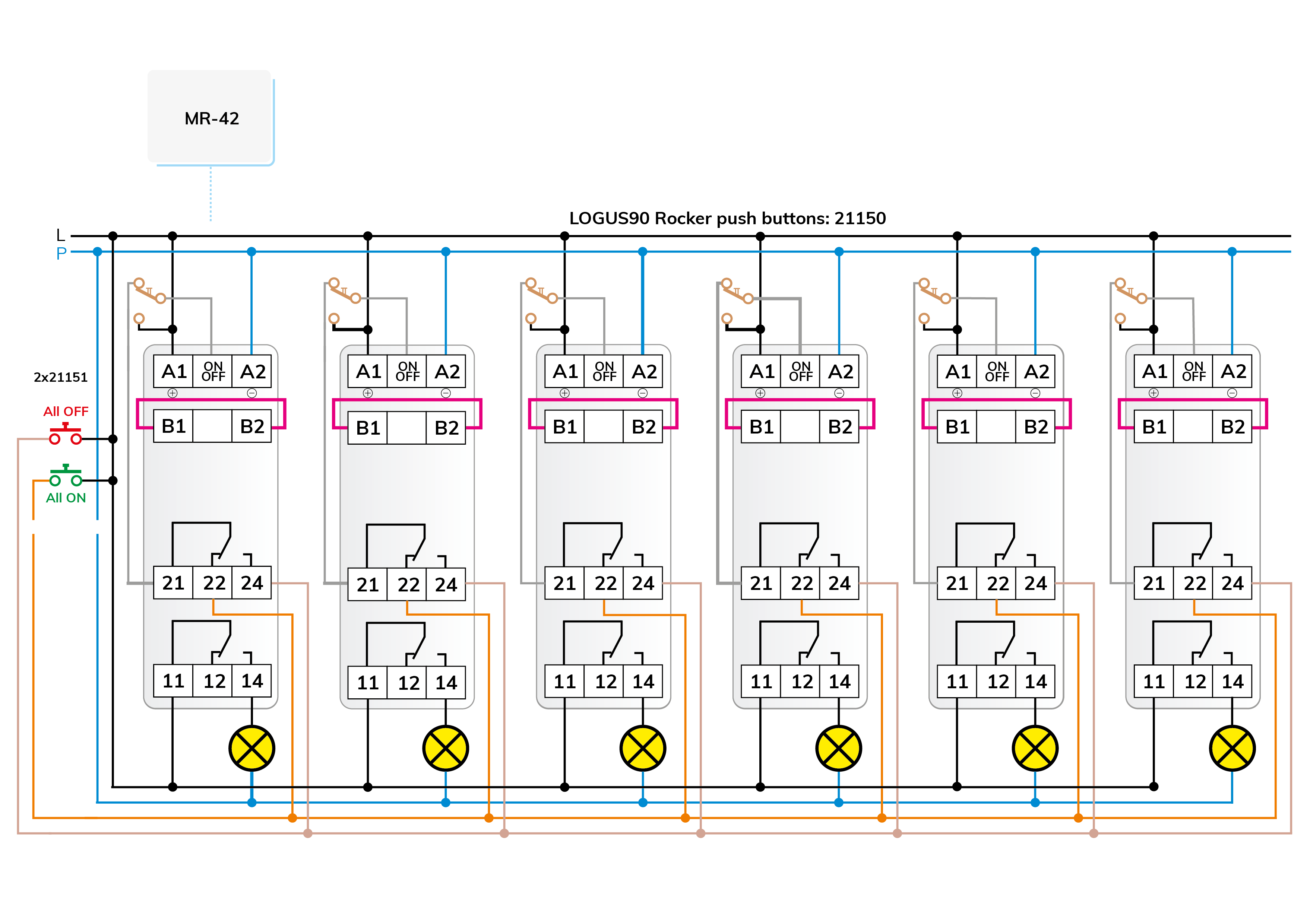
Figure 1 - click to enlarge
The other important difference is that we use the pulse relay type MR-42, with two potential-free and independent changeover contacts, which we have already incorporated several times in our previous circuits. It is basically a pulse relay, but by connecting terminals B1 - B2, we "program" the two relays for parallel operation - see Figure 2. Channel 1 of the pulse relay switches the corresponding lighting circuit, while channel 2 provides information about the status of the given pulse relay to the common control, i.e. it "shows" whether the particular lighting circuit is switched on or off.
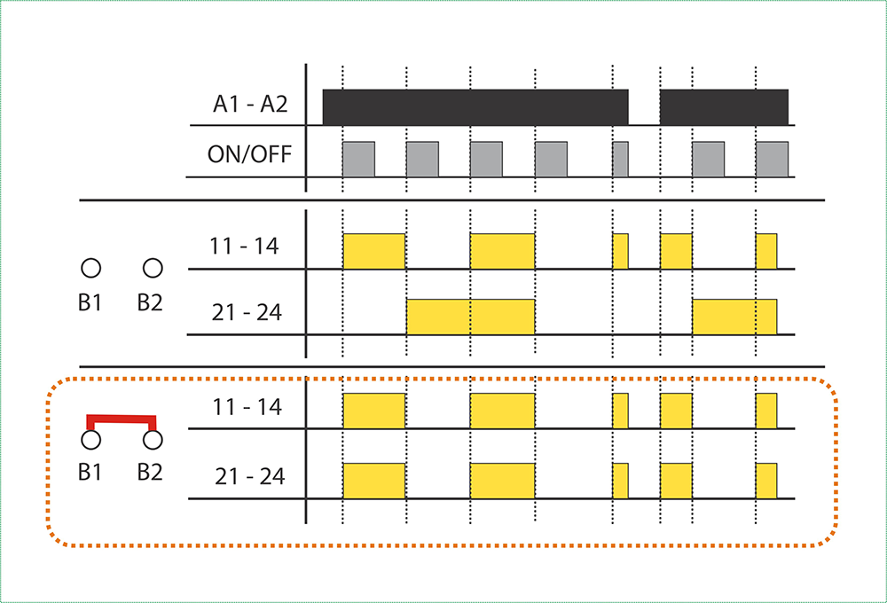
Figure 2 - click to enlarge
The local push buttons can be used to directly change the state of the pulse relay associated with the push button, and in the default state it "enables" the common control in the direction opposite to its current state. Thanks to the toggle contact buttons, joint control can only take effect if the local buttons are in their default position, i.e. not pressed. Only channel 2 of the pulse relay transmits a signal to the ON/OFF input, which is in a state opposite to the function of the pressed "All On" or "All Off" common pushbutton:
When interpreting the operation, consider that the ON/OFF input works on a rising edge, so the pulse relay switches when the control voltage appears, and it doesn't matter how long the voltage remains on it. The relay does not react to switching off the control signal.
The "All On" and "All Off" push buttons designed in the drawing are the LOGUS90 design 21151 normal push button type.
In the connection above, separate push buttons were used for common on and off.
If it's a pulse relay, it would be nice to control everything, including the common control, with a "one-button". In our next letter, we will show you a possibility for this.
In our current letter, we continue our thoughts on the joint control of pulse relay lighting. In the push-button or switch control of "real" smart houses, almost all options can be selected or implemented by programming, and it is even possible to combine them. Thus, a lighting circuit in a smart house can be controlled traditionally, i.e. with a simple single-pole switch and/or with two separate switches and/or with a push button in the form of a pulse relay and/or with a separate on and off push button, as can be seen in the circuit diagram of the previous letter. But you can also manipulate the number of button presses or the duration of the button presses. By further "smartening" the circuit diagram of our previous letter with a small modification, we show how the one-button common on and off can also be solved with pulse relay control.
The circuit diagram in Fig. 3 shows the additions and modifications that are necessary to convert the basic circuit described in the previous letter to a one-button control.
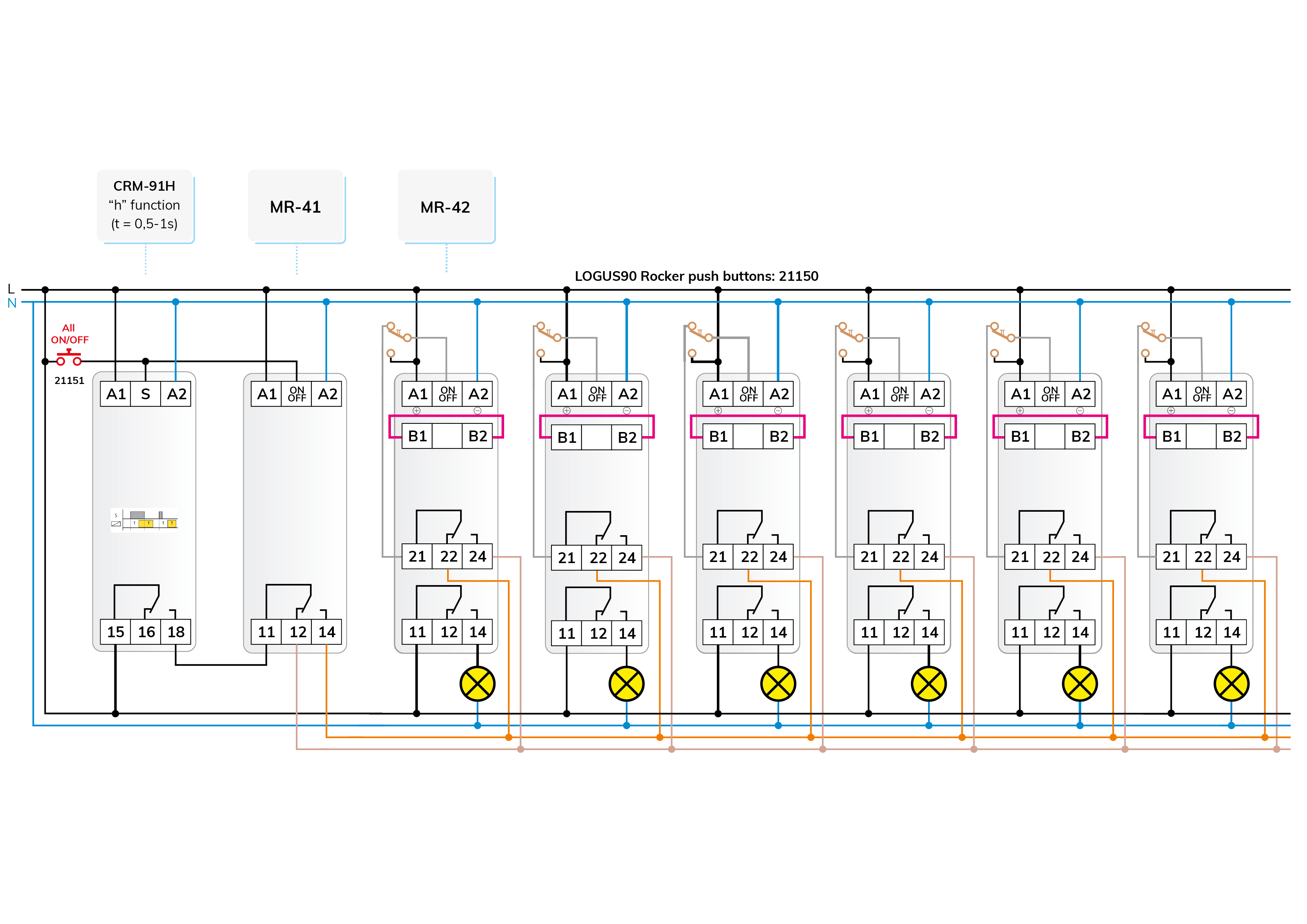
Figure 3 - click to enlarge
The push buttons with change-over contacts remain for independent control, but a traditional NO contact push button is sufficient for joint control. Of course, it is only sufficient if we resolve that there is no voltage on the two common control wires and that no voltage remains in the default position, otherwise, it would not be possible to control the individual circuits independently, - so the common control signal must be sent to the inputs of the relays as a pulse.
This pulse is provided by the already well-known CRM-91H multifunctional time relay, while the on/off one-button common control is provided by an actual pulse relay, the MR-41.
The operation of the independent control is the same as the basic operation of the MR-42 - in parallel mode (B1 - B2 connected), as in the previous connection. The operation of the common control can be clearly seen in the circuit diagram of Figure 3 and the operation diagram of Figure 4.
The switch buttons of the independent control still "enable" the joint control in the idle, default position. By pressing the push button of the common control, the "S" input of the time relay and the ON/OFF input of the MR-41 receive a start signal at the same time. The output of the MR-41 switches, but no voltage appears on it yet, because the output of the time relay does not yet switch to it due to the delayed switching.
When the time relay is set to the "h" function, it will operate with a delay switch on of "t" duration and a release-delay of the same duration "t", i.e. it will delay for "t" with the output turned off, then its output will turn on, which will remain on for "t" and then the relay turns off.
The initial "idle" delay is necessary so that the relays have time to switch to the other state and the pulse relays do not switch incorrectly before switching.
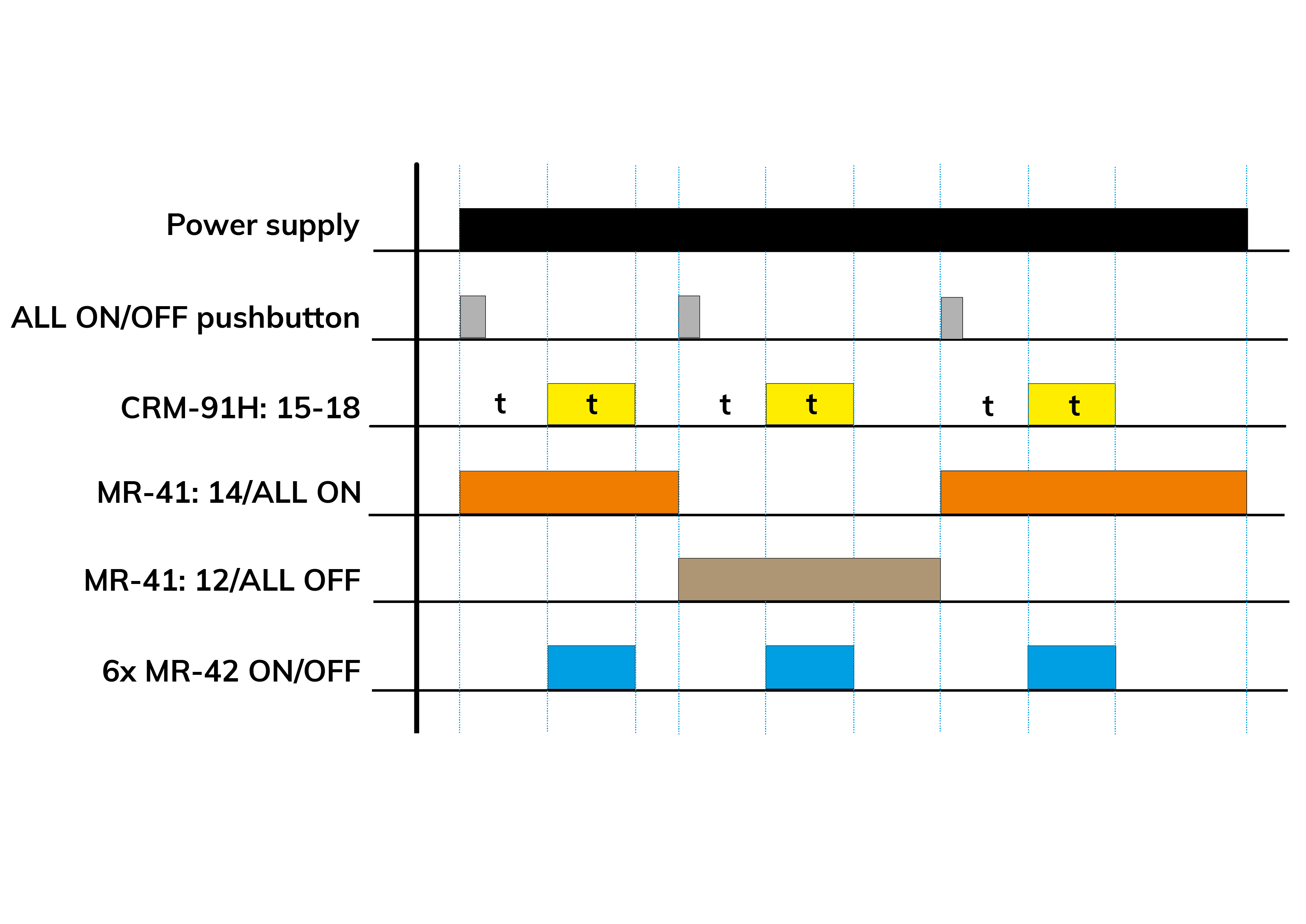
Figure 4 - click to enlarge
The time relay thus supplies the delayed pulse necessary for switching the MR-42 relays, and the changeover contact of the MR-41 stores the state before the next button presses as a digital, one-bit memory.
If the pulse relays controlling the lighting are installed in a switch cabinet, then the push buttons in the rooms are usually connected to the ON/OFF inputs of the relays with two wires per button, which is quite sufficient for control. In the circuit diagrams presented so far, we used pushbuttons with changeover contacts in order to be able to disconnect the local control from the common control wire. However, this requires three wires from the push button. In the following, we present an option for building the already existing 2-wire system with common control.
The two wires coming from the push-buttons are just enough to control one normal relay with a changeover contact per pulse relay - and with that we solved the task. The system supplemented with common control will work like the previously discussed version equipped with changeover contact pushbuttons, only relay contacts take over the role of pushbutton changeover contacts. There is no problem with the solution, only two "little things" arise:
Before we move on, let's look back a little. A few weeks ago, we dealt with logical "OR" and logical "AND" relationships that can be implemented with contacts. For the common control of pulse relays, we must also use such a logical connection, specifically the "OR" gate, so that the relay always switches regardless of where the control signal comes from.
One of the most easily implemented logical "OR" connections may come from the heyday of digital circuits when integrated circuits were not so widespread, but semiconductor technology already existed and the diode as a circuit element was known. It is best known for its use as a rectifier in DC power supplies, but it is also suitable for many other functions, and there are many special types. The diode is a cheap component and can be used to operate according to "OR" logic, but only in DC circuits.
Figure 5 can be used to analyze the operation of the diode's logical connections. You will probably notice that it is quite different from the contact versions. However, they are definitely the same: the results of the logical operations are the same. For our solution, we will use an "OR" connection, but for the sake of completeness, we will also show the "AND" logic of the diode (the solutions may differ according to positive and negative logics, but we will not deal with them here).
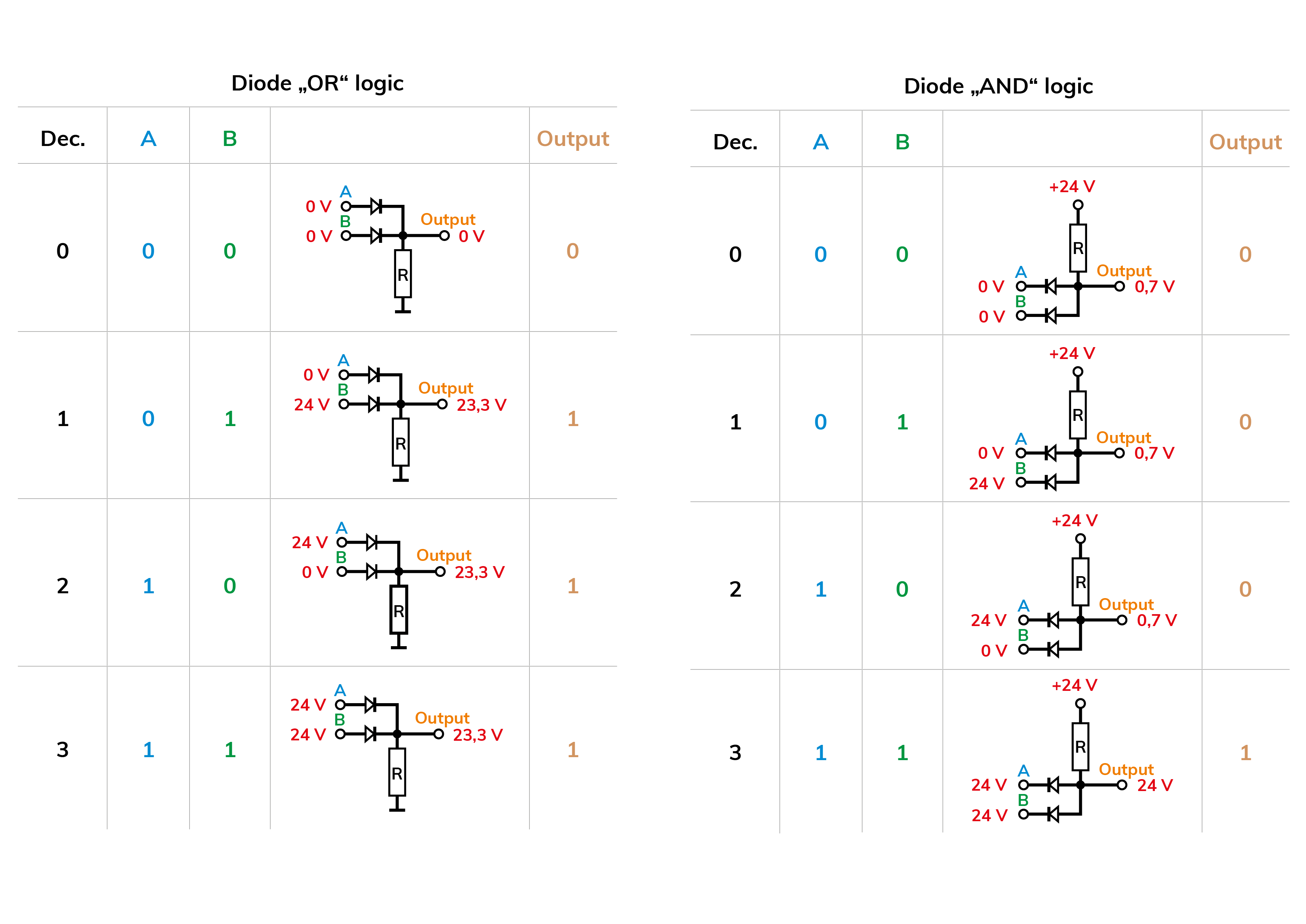
Figure 5 - click to enlarge
The state of the output always depends on whether the diodes are open or closed, i.e. conducting or not. A diode conducts when there is a voltage in the opening direction between its two terminals, the anode and the cathode, which e.g. for silicon diodes, typically 0.5 - 07 V. This voltage is measurable on the diode, therefore it always distorts the output voltage, which is not a problem in this case.
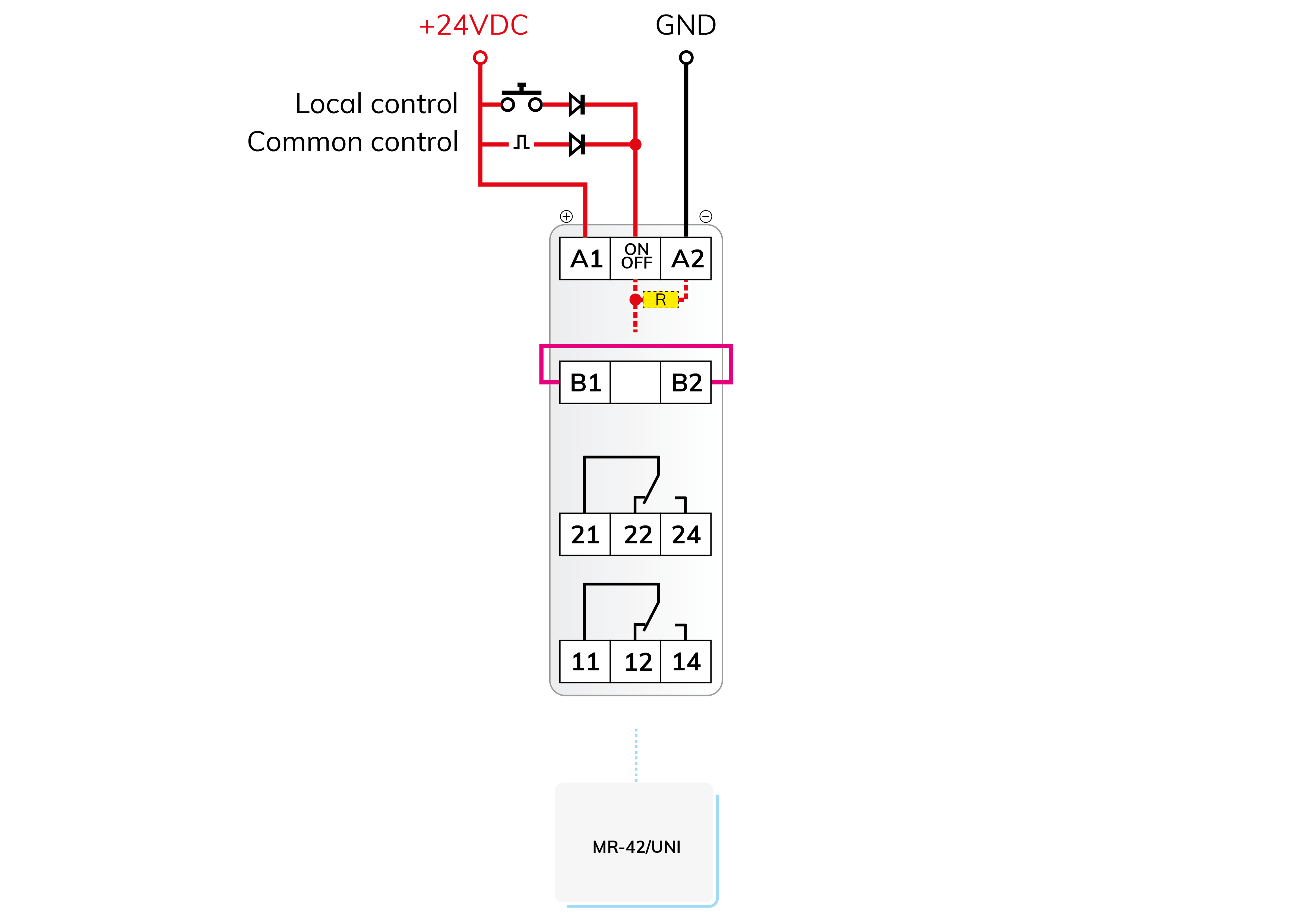
Figure 6 - click to enlarge
Diode logic only works correctly in DC circuits, therefore all devices used in the circuit are UNI-powered (AC/DC 12 - 240 V). The external inputs of the ELKO EP control relays (time relays, pulse relays, etc.) can usually be controlled from the potential of the "A1" terminal point. With an alternating voltage power supply, it does not matter whether phase or neutral is connected to most of these relays.
For DC voltage, however, it is fixed: the positive pole of the DC voltage must be connected to the "A1" terminal, which also means that with DC power supply, the pulse relay monitors the state of the ON/OFF input compared to the GND (A1) point. Since there is no external voltage at the ON/OFF input without control, for the internal circuit the state of the input without control is determined by internal resistance - as shown in the figure.
Of course, the real input circuit consists of slightly more components than this (protection, filtering, etc.), but from a logical point of view, it can be replaced by a resistor to understand the operation (the drawn resistor is only a virtual internal component, it does not need to be and should not be installed!)
According to the ideas above, diode logic connections are not a generally applicable solution. To use them, you need to know the possibilities of the circuits and devices that come into contact with them, the operation of their inputs, and remember that they are only functional in DC circuits in the form discussed here.
Figure 7 shows the circuit diagram of the already well-known six-circuit pulse relay control supplemented with diode logic. Other change comparing it to the previous ones, that all devices are powered by UNI. The CRM-91H and MR-41 can also be 230 V, but then the "All ON/OFF" pushbutton must be connected to the "A1" potential (A1 - A2 is then on a 230 V AC power supply).
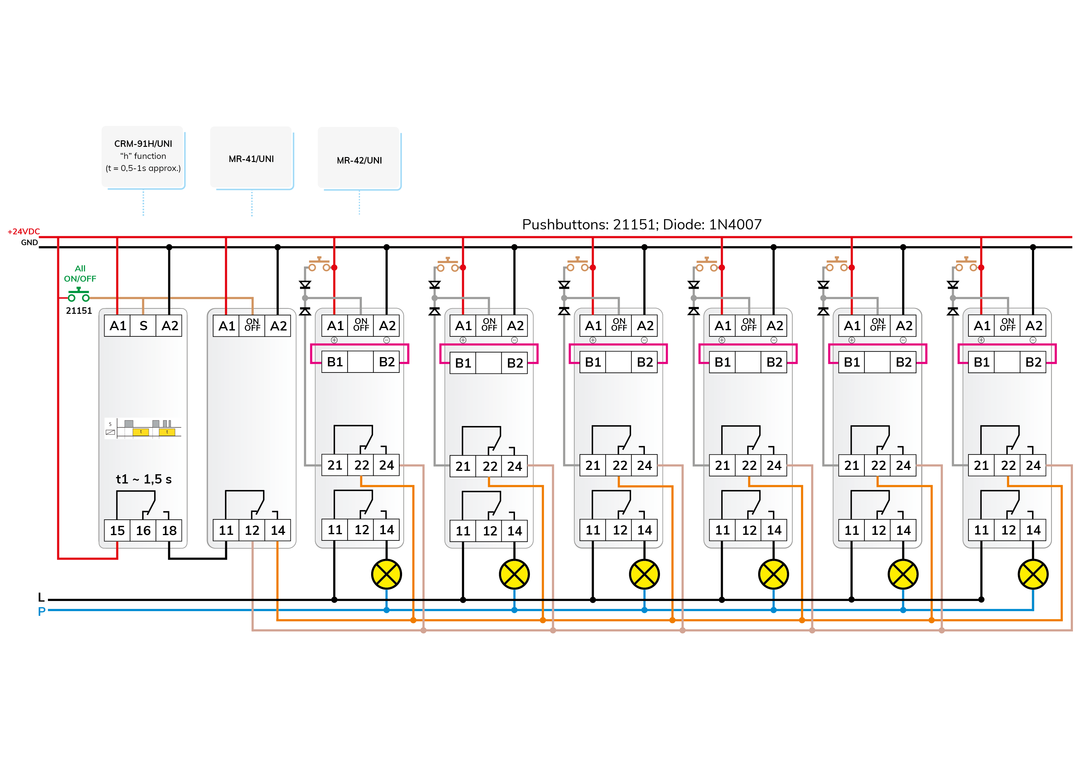
Figure 7 - click to enlarge
Attention! The solutions presented in the articles are illustrated with conceptual circuit diagrams in which, despite repeated inspections or tests under workshop conditions, errors may occur. It is the installer's task and responsibility to check their suitability for a given task and to make any changes! The author and the company do not accept any liability for damages or other problems resulting from the use of the presented solutions. The colors of the wires in the drawings only help for easier transparency, they do not necessarily match the colors of the standard wiring!

 E-shop